Please register to participate in our discussions with 2 million other members - it's free and quick! Some forums can only be seen by registered members. After you create your account, you'll be able to customize options and access all our 15,000 new posts/day with fewer ads.
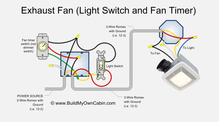
BEFORE: Currently we have a switch for the light, and a switch for the fan. The fan will NOT work unless the light is on. I believe that is what is going on in the wiring diagram I drew. (Also, why is there a green and white wire coming from the light?)
AFTER: What I want to do is just hook one switch straight to the light. And another straight to the fan. That way one can work without the other.
My question is why the hell did they wire it the way they did instead of having the light and fan operate independently of each other? Is there a reason to do something like that?
How many wires are actually available running from the switch box to the ceiling?
I don't know of any good reason why they would have wired it they way they did, unless they got tired of their kids leaving the bathroom fan running all day.
Can't I just have a hot and neutral of one switch go straight to the hot and neutral of the light. And then the hot and neutral from the other switch straight to the fan? [There are separate hots and neutrals for the fan and the light on the assembly.]
Two switches, no timers, I don't care about the fan being left on by mistake.
Never switch neutral. Switches should be single pole, only switch the 'hot' line.
Sure, as long as you use single pole switch only on the hot line, that second diagram of yours doesn't look like it will electrocute anybody. When in doubt, get an electrician.
Are you sure that 'hot' comes in at the junction box where the switches are, and not at the ceiling junction? Are you running new lines in the wall from the switch to the ceiling?
Can't I just have a hot and neutral of one switch go straight to the hot and neutral of the light. And then the hot and neutral from the other switch straight to the fan? [There are separate hots and neutrals for the fan and the light on the assembly.]
Two switches, no timers, I don't care about the fan being left on by mistake.
No problem-
Do you have a "3-wire" coming from the switches to the fan/light location (BLK/RED/WHT+GRD)?
If so, BLK to Light, RED to Fan, WHT to both whites. Just like the illustration that was posted (if the "line" is in the J-box with the switches); a switch is a switch- regardless of the "type".
You're trying to "over simplify" something with MORE wires than you need.
I won't be running any new wires. What was already up there was a sheathing with a black, white, ground ... and then another sheathing also with a black, white, ground. No threes wires (no red ones or anything)... just two sets of the h,n,g.
The new fan/light combo has 6 wires. One labeled hot fan, one labeled hot light, one labeled neutral fan, one labeled neutral light, one labeled fan ground, and the last being light ground.
I will test with my meter tomorrow just to verify the two switches are completely independent of each other. [I think the only reason the fan was relient on the light being on before was because of the way it was wired. Only other possible scenario is switch 2 is dependent on switch 1.]
It will be very simple to do my "after" diagram... I was rather surprised at the set up of the "before" though. Just seemed like an odd way to set it up...
Assuming that both "sets" are tied to the switches, then wire one "set" to the fan, one "set" to the light. In the J-box with the switches all the grounds should be tied together and tied to the switches. All the neutrals "WHT" should be tied together. One BLK goes to one switch, one BLK goes to the other switch.
The "line" coming into the box, the BLK needs two "pigtails"; one for one switch, one for the other. This is probably where the "problem" is with the wiring. By your description, it sounds like the line hot was wired to one switch then to the other. That's why the two elements wouldn't work independently. The "second one" wouldn't work unless the "first one" was on.
And the romex fans criticize us conduit installers for overkill... A proper conduit installation would have a short path from switch to switched device. Just add wires. Easy peasy.
What you need is one hot wire at the switch location and one neutral wire connected to the devices you wish to control. In between the switch and the device, you need a wire.
At the switch location, each switch needs to be fed with a hot. On the other side of the switch, you need to get one wire (called a conductor) to each device you intend to control by a given switch.
In order to find out what you have in terms of wiring, you will need a voltage tester and a continuity tester.
The voltage tester is to check each wire against ground to see what has voltage in it (before turning off the breaker).
The continuity tester is used to identify which wires are going from the switch box to the devices you want to control. You don't want wires that were hot in the test above or neutral wires.
Once you have identified and marked all the non-hot, non-neutral and non-ground wires, you will know if you can do what you want to do.
Please register to post and access all features of our very popular forum. It is free and quick. Over $68,000 in prizes has already been given out to active posters on our forum. Additional giveaways are planned.
Detailed information about all U.S. cities, counties, and zip codes on our site: City-data.com.

 Please register to participate in our discussions with 2 million other members - it's free and quick! Some forums can only be seen by registered members. After you create your account, you'll be able to customize options and access all our 15,000 new posts/day with fewer ads.


") A proper conduit installation would have a short path from switch to switched device. Just add wires. Easy peasy.
A proper conduit installation would have a short path from switch to switched device. Just add wires. Easy peasy.